

The PCI-SIG sends word over this morning that the special interest group has completed their development efforts on the group’s new PCI-Express cabling standard, CopprLink. Designed to go hand-in-hand with PCIe 5.0 and PCIe 6.0, CopprLink defines both internal and external copper cabling for the latest PCIe standards, giving system vendors and assemblers the ability to use wires to connect devices within a system, or even whole systems.
The CopprLink standard is, in practice, a pair of standards sharing the same brand-name under the PCI-SIG umbrella. The internal standard, “CopprLink Internal Cable”, is designed to allow for a new generation of PCIe cables up to 1 meter in length that are capable of sustaining PCIe 5.0 and PCIe 6.0 signaling. Internal CopprLink effectively supplants a host of older internal PCIe cabling standards (including the abandoned OCuLink), which were originally designed for earlier generations of PCIe signaling.
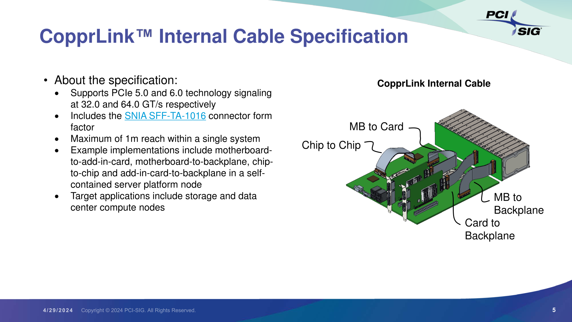
At a high level, internal CopprLink is intended to provide not only host-to-device connectivity, but even more transparent backhaul applications such as motherboard-to-backplane connectivity, and unique applications such as chip-to-chip PCIe connections. In other words, CopprLink allows for cabled PCIe to be used in almost any situation where a PCIe connection needs to be established within a system. Strictly speaking, CopprLink doesn't replace the PCIe CEM connector in any way – but the relatively thick copper cables have less signal loss than PCB traces, making a cabled standard extremely useful even for internal connections. PCI-SIG sees CopprLink cables taking hold in the storage and data center markets, product categories where we already see PCIe cabling in use today.
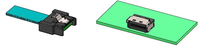
The companion connector standard for internal CopprLink is the SNIA-developed SFF-TA-1016 connector, which bears more than a passing resemblance to the widely-used SFF-8654 (SlimSAS) connector. SFF-TA-1016 is available in x4, x8, and x16 configurations, and while the PCI-SIG doesn’t go so far as to defining widths within their own standard, the connectors available paint a clear picture of the options at hand. Internal CopprLink x4 should be especially popular with storage, as we already see today.

Top: SFF-TA-1016 Family of Connectors (Figure 4-1, Image Courtesy SNIA)
Bottom: Sample SFF-TA-1016 x4 Contact Plug and Recepticle (Figure 4-2, Image Courtesy SNIA)
Meanwhile, the group has also developed an external cabling standard to cover those same PCIe 5.0/6.0 data rates. External CopprLink cables can go up to 2 meters, allowing for board-to-board connections within a rack, and even short rack-to-rack PCIe connections.

The external version of CopprLink also uses a more robust connector, relying on SNIA’s SFF-TA-1032 standard. Like internal/1016, this is available with x4, x8, and x16 configurations, using 44, 68, and 120 positions/pins respectively. The PCI-SIG is expecting this version of the standard to be primarily adopted by the AI/Machine Learning markets, which need to move heaps of data between systems. Notably, however, they don’t really expect the storage market to make use of this spec – instead, they’ll be served by an updated version of the classic PCI Express External Cabling standard.
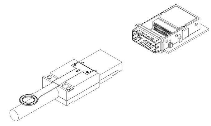
SFF-TA-1032 x16 Plug and Connector (Figure 4-1, Image Courtesy SNIA)
Finally, a bit farther out on the group’s roadmap, PIG-SIG is al... PCIe

Demand for high-performance processors for AI training is skyrocketing, and consequently so is the demand for the components that go into these processors. So much so that SK hynix this week is very publicly announcing that the company's high-bandwidth memory (HBM) production capacity has already sold out for the rest of 2024, and even most of 2025 has already sold out as well.
SK hynix currently produces various types of HBM memory for customers like Amazon, AMD, Facebook, Google (Broadcom), Intel, Microsoft, and, of course, NVIDIA. The latter is an especially prolific consumer of HBM3 and HBM3E memory for its H100/H200/GH200 accelerators, as NVIDIA is also working to fill what remains an insatiable (and unmet) demand for its accelerators.
As a result, HBM memory orders, which are already placed months in advance, are now backlogging well into 2025 as chip vendors look to secure supplies of the memory stacks critical to their success.
This has made SK hynix the secnd HBM memory vendor in recent months to announce that they've sold out into 2025, following an earlier announcement from Micron regarding its HBM3E production. But of the two announcements, SK hynix's is arguably the most significant yet, as the South Korean firm's HBM production capacity is far greater than Micron's. So while things were merely "interesting" with the smallest of the Big Three memory manufacturers being sold out into 2025, things are taking a more concerning (and constrained) outlook now that SK hynix is as well.
SK hynix currently controls roughly 46% - 49% of HBM market, and its share is not expected to drop significantly in 2025, according to market tracking firm TrendForce. By contrast, Micron's share on HBM memory market is between 4% and 6%. Since HBM supply of both companies is sold out through the most of 2025, we're likely looking at a scenario where over 50% of the industry's total HBM3/HBM3E supply for the coming quarters is already sold out.
This leaves Samsung as the only member of the group not to comment on HBM demand so far. Though with memory being a highly fungible commodity product, it would be surprising if Samsung wasn't facing similar demand. And, ultimately, all of this is pointing towards the indusry entering an HBM3 memory shortage.
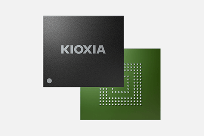
Separately, SK hynix said that it is sampling 12-Hi 36GB HBM3E stacks with customers and will begin volume shipments in the third quarter.
Memory
Demand for high-performance processors for AI training is skyrocketing, and consequently so is the demand for the components that go into these processors. So much so that SK hynix this week is very publicly announcing that the company's high-bandwidth memory (HBM) production capacity has already sold out for the rest of 2024, and even most of 2025 has already sold out as well.
SK hynix currently produces various types of HBM memory for customers like Amazon, AMD, Facebook, Google (Broadcom), Intel, Microsoft, and, of course, NVIDIA. The latter is an especially prolific consumer of HBM3 and HBM3E memory for its H100/H200/GH200 accelerators, as NVIDIA is also working to fill what remains an insatiable (and unmet) demand for its accelerators.
As a result, HBM memory orders, which are already placed months in advance, are now backlogging well into 2025 as chip vendors look to secure supplies of the memory stacks critical to their success.
This has made SK hynix the secnd HBM memory vendor in recent months to announce that they've sold out into 2025, following an earlier announcement from Micron regarding its HBM3E production. But of the two announcements, SK hynix's is arguably the most significant yet, as the South Korean firm's HBM production capacity is far greater than Micron's. So while things were merely "interesting" with the smallest of the Big Three memory manufacturers being sold out into 2025, things are taking a more concerning (and constrained) outlook now that SK hynix is as well.
SK hynix currently controls roughly 46% - 49% of HBM market, and its share is not expected to drop significantly in 2025, according to market tracking firm TrendForce. By contrast, Micron's share on HBM memory market is between 4% and 6%. Since HBM supply of both companies is sold out through the most of 2025, we're likely looking at a scenario where over 50% of the industry's total HBM3/HBM3E supply for the coming quarters is already sold out.
This leaves Samsung as the only member of the group not to comment on HBM demand so far. Though with memory being a highly fungible commodity product, it would be surprising if Samsung wasn't facing similar demand. And, ultimately, all of this is pointing towards the indusry entering an HBM3 memory shortage.
Separately, SK hynix said that it is sampling 12-Hi 36GB HBM3E stacks with customers and will begin volume shipments in the third quarter.
Memory
Lorem Ipsum is simply dummy text of the printing and typesetting industry. Lorem Ipsum has been the industry's.
Demand for high-performance processors for AI training is skyrocketing, and consequently so is the demand for the components that go into these processors. So much so that SK hynix this week is very publicly announcing that the company's high-bandwidth memory (HBM) production capacity has already sold out for the rest of 2024, and even most of 2025 has already sold out as well.
SK hynix currently produces various types of HBM memory for customers like Amazon, AMD, Facebook, Google (Broadcom), Intel, Microsoft, and, of course, NVIDIA. The latter is an especially prolific consumer of HBM3 and HBM3E memory for its H100/H200/GH200 accelerators, as NVIDIA is also working to fill what remains an insatiable (and unmet) demand for its accelerators.
As a result, HBM memory orders, which are already placed months in advance, are now backlogging well into 2025 as chip vendors look to secure supplies of the memory stacks critical to their success.
This has made SK hynix the secnd HBM memory vendor in recent months to announce that they've sold out into 2025, following an earlier announcement from Micron regarding its HBM3E production. But of the two announcements, SK hynix's is arguably the most significant yet, as the South Korean firm's HBM production capacity is far greater than Micron's. So while things were merely "interesting" with the smallest of the Big Three memory manufacturers being sold out into 2025, things are taking a more concerning (and constrained) outlook now that SK hynix is as well.
SK hynix currently controls roughly 46% - 49% of HBM market, and its share is not expected to drop significantly in 2025, according to market tracking firm TrendForce. By contrast, Micron's share on HBM memory market is between 4% and 6%. Since HBM supply of both companies is sold out through the most of 2025, we're likely looking at a scenario where over 50% of the industry's total HBM3/HBM3E supply for the coming quarters is already sold out.
This leaves Samsung as the only member of the group not to comment on HBM demand so far. Though with memory being a highly fungible commodity product, it would be surprising if Samsung wasn't facing similar demand. And, ultimately, all of this is pointing towards the indusry entering an HBM3 memory shortage.
Separately, SK hynix said that it is sampling 12-Hi 36GB HBM3E stacks with customers and will begin volume shipments in the third quarter.
Memory


, which were originally designed for earlier generations of PCIe signaling.</p>
<p align="center"><a href="https://www.anandtech.com/show/21379/pcisig-completes-copprlink-cabling-standard-pcie-50-60-get-wired"><img alt="" src="https://images.anandtech.com/doci/21379/PCI-SIG%20CopprLink%20Press%20Deck_05.png" style="width: 100%;" /></a></p>
<p>At a high level, internal CopprLink is intended to provide not only host-to-device connectivity, but even more transparent backhaul applications such as motherboard-to-backplane connectivity, and unique applications such as chip-to-chip PCIe connections. In other words, CopprLink allows for cabled PCIe to be used in almost any situation where a PCIe connection needs to be established within a system. Strictly speaking, CopprLink doesn't replace the PCIe CEM connector in any way – but the relatively thick copper cables have less signal loss than PCB traces, making a cabled standard extremely useful even for internal connections. PCI-SIG sees CopprLink cables taking hold in the storage and data center markets, product categories where we already see PCIe cabling in use today.</p>
<p>The companion connector standard for internal CopprLink is the SNIA-developed SFF-TA-1016 connector, which bears more than a passing resemblance to the widely-used SFF-8654 (SlimSAS) connector. SFF-TA-1016 is available in x4, x8, and x16 configurations, and while the PCI-SIG doesn’t go so far as to defining widths within their own standard, the connectors available paint a clear picture of the options at hand. Internal CopprLink x4 should be especially popular with storage, as we already see today.</p>
<p align="center"><a href="https://www.anandtech.com/show/21379/pcisig-completes-copprlink-cabling-standard-pcie-50-60-get-wired"><img alt="" src="https://images.anandtech.com/doci/21379/SFF-TA-1016-Connectors_575px.jpg" /></a><br />
<small><em>Top: SFF-TA-1016 Family of Connectors (Figure 4-1, Image Courtesy SNIA)<br />
Bottom: Sample SFF-TA-1016 x4 Contact Plug and Recepticle (Figure 4-2, Image Courtesy SNIA)</em></small><br />
<a href="https://www.anandtech.com/show/21379/pcisig-completes-copprlink-cabling-standard-pcie-50-60-get-wired"><img alt="" src="https://images.anandtech.com/doci/21379/SFF-TA-1016-x4_575px.jpg" /></a></p>
<p>Meanwhile, the group has also developed an external cabling standard to cover those same PCIe 5.0/6.0 data rates. External CopprLink cables can go up to 2 meters, allowing for board-to-board connections within a rack, and even short rack-to-rack PCIe connections.</p>
<p align="center"><a href="https://www.anandtech.com/show/21379/pcisig-completes-copprlink-cabling-standard-pcie-50-60-get-wired"><img alt="" src="https://images.anandtech.com/doci/21379/PCI-SIG%20CopprLink%20Press%20Deck_06.png" style="width: 100%;" /></a></p>
<p>The external version of CopprLink also uses a more robust connector, relying on SNIA’s SFF-TA-1032 standard. Like internal/1016, this is available with x4, x8, and x16 configurations, using 44, 68, and 120 positions/pins respectively. The PCI-SIG is expecting this version of the standard to be primarily adopted by the AI/Machine Learning markets, which need to move heaps of data between systems. Notably, however, they don’t really expect the storage market to make use of this spec – instead, they’ll be served by an updated version of the classic PCI Express External Cabling standard.</p>
<p align="center"><a href="https://www.anandtech.com/show/21379/pcisig-completes-copprlink-cabling-standard-pcie-50-60-get-wired"><img alt="" src="https://images.anandtech.com/doci/21379/SFF-TA-1032-Connector_575px.jpg" /></a><br />
<small><em>SFF-TA-1032 x16 Plug and Connector (Figure 4-1, Image Courtesy SNIA)</em></small></p>
<p>Finally, a bit farther out on the group’s roadmap, PIG-SIG is al... PCIe)
, which were originally designed for earlier generations of PCIe signaling.</p>
<p align="center"><a href="https://www.anandtech.com/show/21379/pcisig-completes-copprlink-cabling-standard-pcie-50-60-get-wired"><img alt="" src="https://images.anandtech.com/doci/21379/PCI-SIG%20CopprLink%20Press%20Deck_05.png" style="width: 100%;" /></a></p>
<p>At a high level, internal CopprLink is intended to provide not only host-to-device connectivity, but even more transparent backhaul applications such as motherboard-to-backplane connectivity, and unique applications such as chip-to-chip PCIe connections. In other words, CopprLink allows for cabled PCIe to be used in almost any situation where a PCIe connection needs to be established within a system. Strictly speaking, CopprLink doesn't replace the PCIe CEM connector in any way – but the relatively thick copper cables have less signal loss than PCB traces, making a cabled standard extremely useful even for internal connections. PCI-SIG sees CopprLink cables taking hold in the storage and data center markets, product categories where we already see PCIe cabling in use today.</p>
<p>The companion connector standard for internal CopprLink is the SNIA-developed SFF-TA-1016 connector, which bears more than a passing resemblance to the widely-used SFF-8654 (SlimSAS) connector. SFF-TA-1016 is available in x4, x8, and x16 configurations, and while the PCI-SIG doesn’t go so far as to defining widths within their own standard, the connectors available paint a clear picture of the options at hand. Internal CopprLink x4 should be especially popular with storage, as we already see today.</p>
<p align="center"><a href="https://www.anandtech.com/show/21379/pcisig-completes-copprlink-cabling-standard-pcie-50-60-get-wired"><img alt="" src="https://images.anandtech.com/doci/21379/SFF-TA-1016-Connectors_575px.jpg" /></a><br />
<small><em>Top: SFF-TA-1016 Family of Connectors (Figure 4-1, Image Courtesy SNIA)<br />
Bottom: Sample SFF-TA-1016 x4 Contact Plug and Recepticle (Figure 4-2, Image Courtesy SNIA)</em></small><br />
<a href="https://www.anandtech.com/show/21379/pcisig-completes-copprlink-cabling-standard-pcie-50-60-get-wired"><img alt="" src="https://images.anandtech.com/doci/21379/SFF-TA-1016-x4_575px.jpg" /></a></p>
<p>Meanwhile, the group has also developed an external cabling standard to cover those same PCIe 5.0/6.0 data rates. External CopprLink cables can go up to 2 meters, allowing for board-to-board connections within a rack, and even short rack-to-rack PCIe connections.</p>
<p align="center"><a href="https://www.anandtech.com/show/21379/pcisig-completes-copprlink-cabling-standard-pcie-50-60-get-wired"><img alt="" src="https://images.anandtech.com/doci/21379/PCI-SIG%20CopprLink%20Press%20Deck_06.png" style="width: 100%;" /></a></p>
<p>The external version of CopprLink also uses a more robust connector, relying on SNIA’s SFF-TA-1032 standard. Like internal/1016, this is available with x4, x8, and x16 configurations, using 44, 68, and 120 positions/pins respectively. The PCI-SIG is expecting this version of the standard to be primarily adopted by the AI/Machine Learning markets, which need to move heaps of data between systems. Notably, however, they don’t really expect the storage market to make use of this spec – instead, they’ll be served by an updated version of the classic PCI Express External Cabling standard.</p>
<p align="center"><a href="https://www.anandtech.com/show/21379/pcisig-completes-copprlink-cabling-standard-pcie-50-60-get-wired"><img alt="" src="https://images.anandtech.com/doci/21379/SFF-TA-1032-Connector_575px.jpg" /></a><br />
<small><em>SFF-TA-1032 x16 Plug and Connector (Figure 4-1, Image Courtesy SNIA)</em></small></p>
<p>Finally, a bit farther out on the group’s roadmap, PIG-SIG is al... PCIe | https://compbuddey.blogspot.com/2024/05/pci-sig-completes-copprlink-cabling_4.html)
, which were originally designed for earlier generations of PCIe signaling.</p>
<p align="center"><a href="https://www.anandtech.com/show/21379/pcisig-completes-copprlink-cabling-standard-pcie-50-60-get-wired"><img alt="" src="https://images.anandtech.com/doci/21379/PCI-SIG%20CopprLink%20Press%20Deck_05.png" style="width: 100%;" /></a></p>
<p>At a high level, internal CopprLink is intended to provide not only host-to-device connectivity, but even more transparent backhaul applications such as motherboard-to-backplane connectivity, and unique applications such as chip-to-chip PCIe connections. In other words, CopprLink allows for cabled PCIe to be used in almost any situation where a PCIe connection needs to be established within a system. Strictly speaking, CopprLink doesn't replace the PCIe CEM connector in any way – but the relatively thick copper cables have less signal loss than PCB traces, making a cabled standard extremely useful even for internal connections. PCI-SIG sees CopprLink cables taking hold in the storage and data center markets, product categories where we already see PCIe cabling in use today.</p>
<p>The companion connector standard for internal CopprLink is the SNIA-developed SFF-TA-1016 connector, which bears more than a passing resemblance to the widely-used SFF-8654 (SlimSAS) connector. SFF-TA-1016 is available in x4, x8, and x16 configurations, and while the PCI-SIG doesn’t go so far as to defining widths within their own standard, the connectors available paint a clear picture of the options at hand. Internal CopprLink x4 should be especially popular with storage, as we already see today.</p>
<p align="center"><a href="https://www.anandtech.com/show/21379/pcisig-completes-copprlink-cabling-standard-pcie-50-60-get-wired"><img alt="" src="https://images.anandtech.com/doci/21379/SFF-TA-1016-Connectors_575px.jpg" /></a><br />
<small><em>Top: SFF-TA-1016 Family of Connectors (Figure 4-1, Image Courtesy SNIA)<br />
Bottom: Sample SFF-TA-1016 x4 Contact Plug and Recepticle (Figure 4-2, Image Courtesy SNIA)</em></small><br />
<a href="https://www.anandtech.com/show/21379/pcisig-completes-copprlink-cabling-standard-pcie-50-60-get-wired"><img alt="" src="https://images.anandtech.com/doci/21379/SFF-TA-1016-x4_575px.jpg" /></a></p>
<p>Meanwhile, the group has also developed an external cabling standard to cover those same PCIe 5.0/6.0 data rates. External CopprLink cables can go up to 2 meters, allowing for board-to-board connections within a rack, and even short rack-to-rack PCIe connections.</p>
<p align="center"><a href="https://www.anandtech.com/show/21379/pcisig-completes-copprlink-cabling-standard-pcie-50-60-get-wired"><img alt="" src="https://images.anandtech.com/doci/21379/PCI-SIG%20CopprLink%20Press%20Deck_06.png" style="width: 100%;" /></a></p>
<p>The external version of CopprLink also uses a more robust connector, relying on SNIA’s SFF-TA-1032 standard. Like internal/1016, this is available with x4, x8, and x16 configurations, using 44, 68, and 120 positions/pins respectively. The PCI-SIG is expecting this version of the standard to be primarily adopted by the AI/Machine Learning markets, which need to move heaps of data between systems. Notably, however, they don’t really expect the storage market to make use of this spec – instead, they’ll be served by an updated version of the classic PCI Express External Cabling standard.</p>
<p align="center"><a href="https://www.anandtech.com/show/21379/pcisig-completes-copprlink-cabling-standard-pcie-50-60-get-wired"><img alt="" src="https://images.anandtech.com/doci/21379/SFF-TA-1032-Connector_575px.jpg" /></a><br />
<small><em>SFF-TA-1032 x16 Plug and Connector (Figure 4-1, Image Courtesy SNIA)</em></small></p>
<p>Finally, a bit farther out on the group’s roadmap, PIG-SIG is al... PCIe&body=https://compbuddey.blogspot.com/2024/05/pci-sig-completes-copprlink-cabling_4.html)
0 Comments